We are very lucky to have a family friend who is as generous as she is artistic. Earlier this year she was kind enough to paint us a "season tree" spanning four individual 12"x12" canvases. In order to do the painting justice and display it properly my wife asked if I could build a custom frame. We decided on walnut to match the color palette of the artwork and because I was itching to dig into the stash of beautiful wide walnut I picked up last fall.
Lex helped me get started by picking out one of the smaller boards from the stack and cutting it down to rough length by hand.

The board was over 14" wide and she tired out about half way through so I took over with Eli's help while Lex photographed the process.

The board we selected had a decent sized crack down the center so we split it the full length and then laid out reference lines along the grain to yield nice straight grained stock for the long narrow pieces of the frame. With the kids back in the house I then ripped the pieces along those lines and jointed the cut edges.

I then flattened and thicknessed the stock and ripped the opposite edge parallel to the reference edge. These two pieces will yeild the 4 outside rails and 2 inner dividers.

I did some head scratching to figure out the best way to create the rabbets on the frame edge pieces while leaving a very narrow ~1/8" overhang on the front face. I ended up ripping the larger piece in half and then ripping a slot along each of the 4 resulting edges.

An outer frame piece was then cut from each side. The thin strip remaining along the edge will be removed later.

The inner dividers were also a bit tricky in that the final pieces needed to end up as a 1" tall by 1/2" wide "T" shape with each leg being just a bit over 1/8" thick. In order to create this shape and also ensure that the stock was safe to work later on while cutting the joinery I used a similar technique to the edge pieces and ripped a pair of slots along each edge of the workpiece to define the center section of the "T" shape.

The individual dividers were then cut free from the larger piece.

The next step was to miter the outer edges so I dialed in the miter gauge and set a stop block to ensure all 4 pieces end up the exact same length.

Here you can see from the rear view of a corner of the frame how the rabbets will be created when the thin strips of scrap are removed from the inside edges, leaving only the 1/8" thick front face to cover the edge of the canvas.

A test fit proved that the miter joints were good with all 4 corners meeting nice and tight.

After planing the show surfaces smooth I then used a marking gauge to scribe a line where the thin scrap piece will be removed.

This piece was then cut free with a few whacks with a wide chisel. The rough surface was then cleaned up with a shoulder plane.

In order to ensure nice tight miter joints when gluing up the frame I decided to add 45 degree glue blocks to each corner. This allows a clamp to be applied directly across the miter to ensure a good tight joint. It is a bit of work to prep the glue blocks, glue them on the day before the frame glue-up, and then remove them afterwards but it makes the glue-up process easier and the results are worth the extra effort.


A few dabs of glue and 4 clamps later and the frame was glued up. Time to move onto the joinery for the dividers.

Each divider is joined to the outside pieces of the frame with a form of bridle joint, essentially a through mortise and tenon with the bottom side open. I started fitting these joints by cutting a slot in the dead center of each outside piece that was half the depth of the piece and as wide as the bottom leg of the "T" shaped dividers was thick. I then trimmed off the top half of one end of the divider piece so that it fit into the slot. I then marked the top of the "T" where it met the overhang along the edge piece so that it could be chiseled away to form one end of the joint.

With one end complete I marked the other end with a knife and repeated the same procedure. Below you can see how the top of the "T" is preventing the divider from seating all the way into the slot.

Here is a detail shot showing how the top of the "T" was marked with a knife and trimmed away with a chisel. Here you can also see that I left the scrap pieces on the "T" making it more of a flat topped "M" shape so that it was stable enough to run over the table saw later.
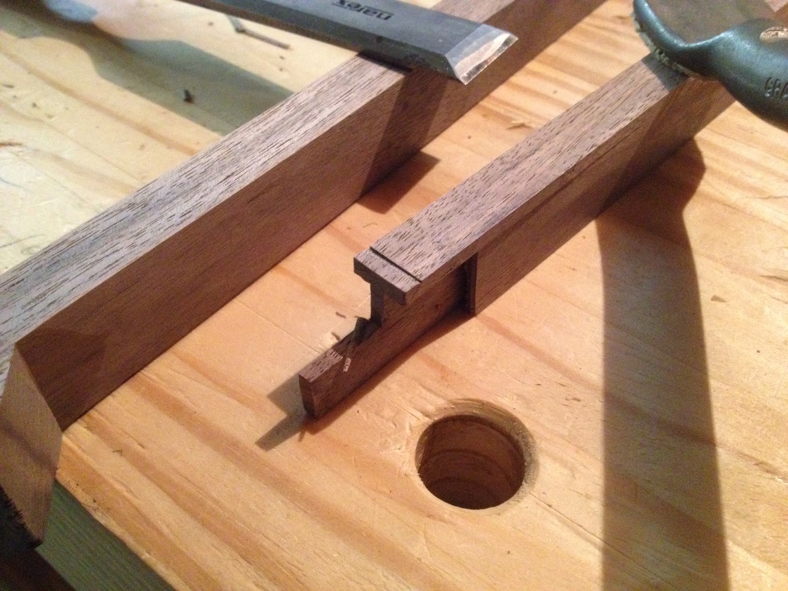
Below you can see the second side of the joint coming together nice and tight. It is amazing how accurate you can be when working to a knife line.

With the joints fitted to connect each divider to its outer two edges individually it was time to focus on joining them together in the center of the frame. This process started with removing the side scraps from the center section of each divider. This allowed me to fit these joints while again leaving a stable square piece to run over the table saw.

I started this joint by laying both dividers in place aligned with their edge joints and marking the location of a slot in the top face of the lower piece. I then cut this slot to half the depth of the divider on the table saw and test fit the pieces as shown below. This allowed me to mark the exact location of the slot that needed to be cut in the bottom half of the top piece. With both slots cut the top divider dropped down until the top of the "T" rested on the top of the bottom divider. I then scribed along those edges with a knife to mark the section of the bottom piece that needs to be removed. This may sound complicated but it was actually very simple to execute.

With the top of the "T" marked out I removed most of the waste with the table saw leaving just a bit of wood inside of the knife lines which I then cleaned up with a chisel.

This was the most critical joint of the whole project and any slop or error would result in a gap with no reasonable option to fix it. In the end the process of overlaying the mating pieces and marking them out directly with knife lines paid off and the joint came together with a nice tight friction fit.

With the joinery done I shifted to prepping the frame for final glue-up and finishing. I removed the bulk of the corner glue blocks at the bandsaw.

I then trimmed away the rest with the block plane and a few final passes with the smoother.

I had been handling the frame quite a bit while working on the joinery and the glued miter joints were nice and solid but I don't trust them over the long run so I decided to add some reinforcing splines across the corners. I slapped together a quick and dirty jig allow me to cut the slots for these splines on the table saw. Note that you want to use a flat top grind rip blade for this to ensure the resulting saw kerf has a flat bottom rather than the jagged corners left by most combination or crosscut blades.

Here you can see an example of the flat bottomed slot cut across the corners.

I finished up this step by planing down some scraps of walnut to fit snugly into these slots and glued them in.

Next I glued in the center dividers one at a time using a pipe clamp to pull the joints nice and tight.


Once the glue was dry I trimmed off the corner splines and protruding sections at the divider joints with the bandsaw and planed everything flush.


After a bit of cleanup work with the smooth plane, card scraper, and just a few strokes with some 220 sandpaper the frame was ready for finish. I wiped on 3 coats of shellac, sanding before the final coat, and topped it off with some paste wax buffed in with a scotchbrite pad.

I considered a few options for mounting the canvases to the frame but ended up settling on hot glue. It may not be how this is normally done but it was simple, reversible, and seems to be holding up well so far.

My low light cell phone photography leaves a lot to be desired but I'm really happy with how the end result turned out. The painting is gorgeous and I think the simple walnut frame compliments it well without getting in the way.

In terms of board feet of lumber used this is one of the smallest projects I've done to date but the small delicate joinery was a lot of fun. This project took me just over a month to complete which is pretty quick by my standards. My final observation was that walnut is absolutely wonderful to work with. I am very excited to finish up Lex's oak bookshelf that has been dragging on since late last summer and then shift gears to focusing on the walnut bed the wife has requested.


