With the bench assembled I was excited to work on the leg vise. I started by mounting the screw hardware to the leg, being careful to center the screw in the clearance hole.

Next I dug through my pile of oak 2x12's to find the rough stock needed for the leg vise chop. I managed to find a decent piece with only one small knot.

I cut out the section I was interested in by hand since my power miter saw won't handle a 12" wide board and a hand saw is just easier than dragging out the circular saw.

The piece had a few stains but I figured they were only skin deep.

This piece was much too large for my 6" jointer so I put the bench to use and flattened one side by hand with the planes. I reviewed the board and marked the high spots with chalk.

I planed down the high spots with the jack plane and to get things a bit less wonky and then used the winding sticks to identify any twist along the length of the board.

Once one side was fairly flat and twist free I sent the board through the planer with that face down as the reference to get the other side flat and parallel. With the second side completely flat I flipped the board to clean up the 1st side that was only partially planed to roughly flat by hand. All-in-all this process was pretty quick and worked great to flatten and dress this large piece.

Here you can see the stock looks great and all the staining planed out nicely. This is just a vise on a workbench but I still put some thought into the aesthetics and laid out the chop to center the grain pattern along the vertical axis.

I used a marking gauge to find the center of the chop to mark the location of the hole for the vise screw.

I bored out the screw hole with the auger and brace. I still love my Milwaukee drill for driving screws but I'm completely sold on a brace and a decent auger bit for drilling holes of any decent size in wood.

At this point I couldn't resist mounting the chop and testing it out with a spacer block in the bottom to serve as the fulcrum.

The long term solution for the fulcrum is the combination of a parallel guide with a variety of holes for a pin to bear against the front of the leg. This parallel guide is joined to the vise chop with a wedged through mortise and tenon.

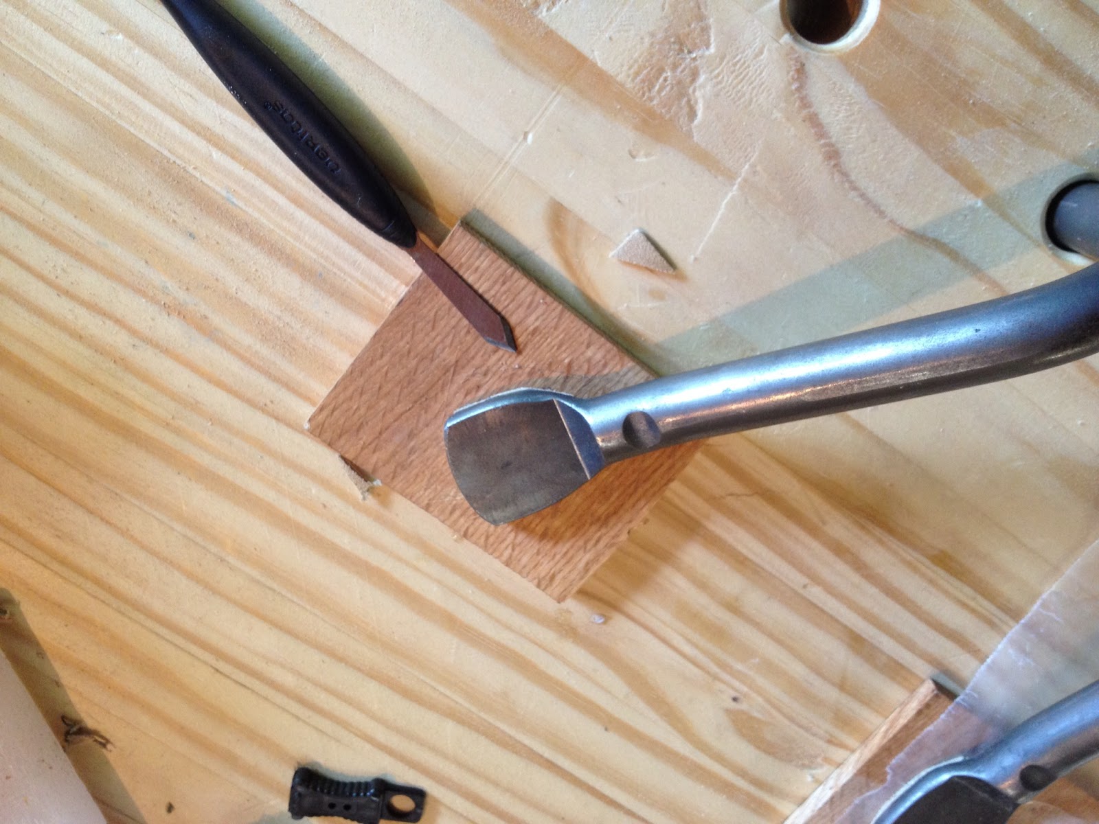
Here I am laying out the location of the mortise in the vise chop.

I used the width of the mortise chisel to define the exact width of the mortise. The tenon will then be cut to fit the mortise.

I again bored out a majority of the waste with a brace and auger bit, working from both sides so that any deviation from vertical would be minimized.

Chopping out the ends...

...and paring down the side walls. Not too bad for my second hand cut mortise.

After completing the mortise I started laying out the tenon on the parallel guide by defining the length of the tenon to be just a touch longer than the thickness of vise chop.

I then "cheated" and used a dado stack in the table saw to cut the tenon. I still don't trust my ability to saw to a line enough to cut the shoulders and cheeks by hand.

After a few minor tweaks to the depth of cut on the dado stack it fits.

The tenon is just a bit proud of the face of the vise chop. This will be planed flush after it is installed.

Just for kicks I installed the vise chop and screw with the parallel guide just friction fit and the vise traveled in and out nice and smooth.

The next step was to add the array of pin holes to the parallel guide so that the vise can be easily adjusted to clamp pieces of different thicknesses. I marked a line parallel to each edge and then stepped off the location of each hole with dividers.

More boring with the brace and auger bit and the parallel guide was done.

In order to lighten the vise chop and make it a bit more attractive trimmed off the lower corners with a tapering jig on the table saw.


The through tenon joining the parallel guide to the vise chop will be wedged. I chiseled a very small flare to the outside of the mortise so that when the wedges are driven in the tenon will be locked into the mortise.

I cut saw kerf into each end of the tenon to receive the wedges.

Here are all the parts ready for assembly.

And here are the parts after assembly.

Once the glue had cured I sawed the wedges close to flush and planed the end of the tenon flush with the face of the vise chop.

If you look carefully you can see the faint variations in appearance of the wedges. In hindsight I should have used something other than oak for the wedges just to create more contrast and make them more visible.

To help the vise grip better I added a piece of suede to both the vise chop and the mating front edge of the bench with contact cement.

I used contact cement rather than normal wood glue as it should be easier to remove if the suede ever needs to be replaced.

I didn't have the vise screw installed at this point so I just used a pair of clamps to apply pressure to set the contact cement. I added a piece of wax paper between the two pieces of suede to prevent them from sticking together.

Once the suede was attached I finished the leg vise assembly with two coats of a mix of equal parts boiled linseed oil, oil based poly, and mineral spirits.

And here it is finished and installed on the bench.

While I had the contact cement and suede out I decided to add pads to the face of both of the holdfasts.

I cut the suede to just a bit larger than the holdfast and then clamped them down to set the contact cement.

When the glue had set I trimmed around the edges with a marking knife.
It worked out pretty well and the suede pads helped the holdfasts to grip better and provided a bit of protection to prevent denting or marking the workpiece being clamped.

Shifting back to the leg vise the only missing piece was a pin to act as the fulcrum. I decided to try to make a quick and dirty pin out of a long 3/8" bolt threaded into a block of oak as the handle.

The galvanized coating on the bolt looks like crap so I soaked it in vinegar for a few days to strip it down to bare steel.

The result should look much more at home on a 17th century style workbench.

The initial shaping of the handle was done on the table saw with the blade set to 45 degrees.

The handle is still long to allow it to be clamped in the vise for some final shaping. The bolt is installed ready to have the head ground off.

After about 5 minutes on the bench grinder the pin now has a nice round tip and is usable. I still need to refine the shape of the handle and apply a few coats of finish but I decided this was good enough for now.

The next and last piece to be made was the sliding deadman that will work along with the leg vise to hold long boards on edge. I cut out a rough blank of oak from the piece leftover from the leg vise chop.

I followed the same hybrid flattening/planing procedure discussed above to get it flat and smooth.

The front rail of the bench has a triangular cross section feature on its top edge to act as a guide rail. I cut a mating triangular notch into the bottom of the deadman with the table saw setup shown below.

I used the dado stack on the table saw to remove the material at the top of the deadman to form the tongue that fits into the slot that was routed into the underside of the benchtop. The deadman can then slide up and into the slot and then drop down onto the guide rail. This test fit proved that it not only fit but also slid back and forth nicely.

I used a flexible steel ruler and a few brad nails to layout a nice curve on each edge of the deadman. This curve lightens the piece and also allows you to get your hand in between the deadman and the bench leg even if it is pushed up tight against the leg.

With the curves defined I also laid out the array of holes that will hold pegs or holdfasts at a variety of heights to support boards or panels of just about any size.

More boring holes.

A bit of work on the bandsaw and the deadman is getting close to done.

And here it is hanging out on the bench. I still need to clean up the curves with a spokeshave and then hit the faces with a smoothplane before applying a couple coats of finish but it is usable at this point.

I had a bit of extra suede left over so I padded the end vise too.

The pieces were a bit smaller than the vise chop but they are big enough to cover the entire metal vise jaw which was my main goal as I had noticed when I was using the end vise that I was getting paint from the metal jaw on the workpieces. The suede should fix that problem.

At this point there are a few remaining odds and ends to finish or cleanup but the bench is fully functional. Just in time to help Lon flatten a pair of boards that are two wide for the power jointer that he is planning to glue up for the top of a dresser. In the picture below you can see the leg vise and a holdfast in the right leg being used to hold a 12"+ wide board as he planes the edge. I'm not even sure I would have attempted this without the new bench. Lex was clearly impressed :).

I can't wait to finish up the last few details (finish the details on the deadman and leg vise pin, final flattening of the benchtop, possibly add a shelf between the stretchers, and apply a few coats of finish to the bench.) and put this thing to use on a few non-bench related projects.